

The prop you select must synch with both your engine and your hull.
Do you feel a vibration when your boat is running at speed? Does the vibration occur at high speeds and go away at low speeds? Or does it occur at low speeds and disappear at higher speeds? If it only appears at high speeds, your propeller may be too close to the hull, or the prop may have a bent or damaged blade. If the problem appears at low speeds it might be that the shape of the hull is causing a change in pressure in the area where the propeller is operating.
There are many factors that affect the interaction of a propeller and the hull. They include the hull shape, the proximity of the hull to the propeller, or whether the propeller is operating directly behind the hull (in the case of a single prop) or to one side of the hull in the case of a twin screw vessel. In addition, the speed of the vessel must be taken into account. Slow-speed boats generally have different problems than do vessels that get on plane and run at planing speeds. Boats that run at extremely high speeds have even more complex issues resulting from hull/propeller interactions.
If your hull and propeller are not optimized, they could be costing you money. For example, your small fishing boat’s skeg/keel is large enough to protect the single propeller should you go aground. However, it might also be reducing the efficiency of the propeller, meaning that replacing a dinged or bent propeller could be less expensive than having a skeg to protect it.
Inboard Installations
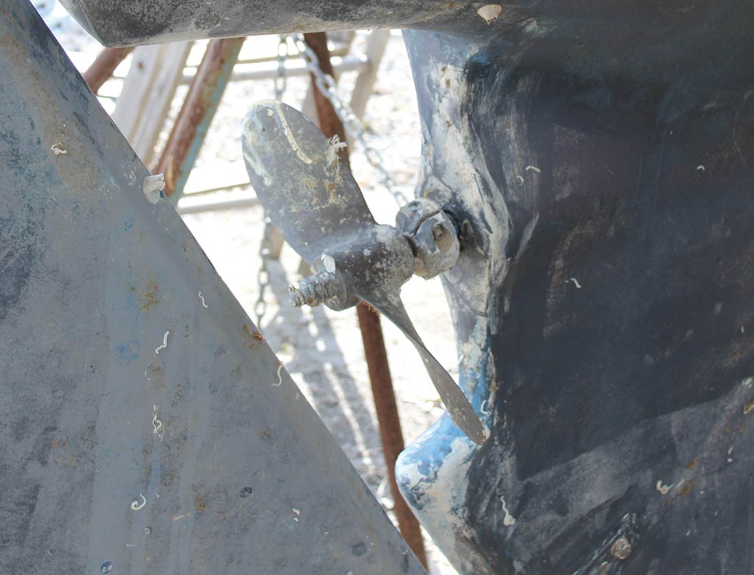
Having a hull, keel or other obstruction in front of the propeller causes loss of efficiency. The actual loss varies with the size of the obstruction. For example, the rather extreme example shown in Figure 1 pictures a two-blade propeller behind a thick skeg or keel. Every time the propeller is vertical the water flow is blocked by the skeg producing vibrations that could reduce the efficiency of the propeller by as much as 50 percent.

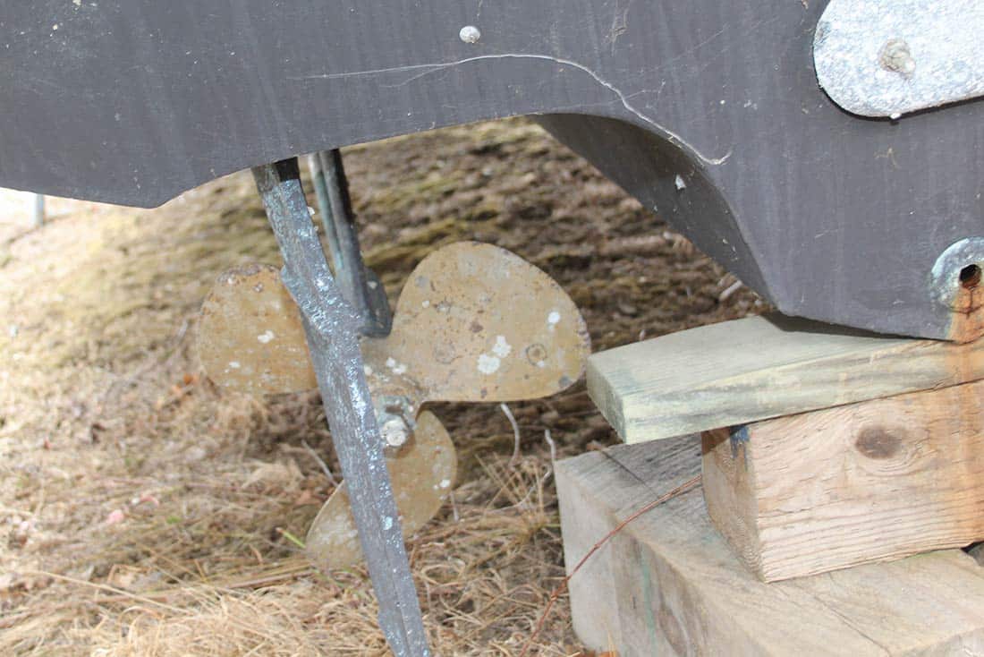
Figure 2 shows a better solution. Here, a three-bladed propeller is used and moved farther away from the keel. Another solution would be to taper the keel where the water flows toward the keel, but this is not always possible when the keel is laminated during the building process. (When the boat is being built, the person laying the fiberglass into the hull might have to get their hand down into the skeg area to be sure it is sufficiently reinforced.) On this boat, the turning radius would be enhanced by extending the rudder up to the hull at the top to get more “end plate” effect from the hull.

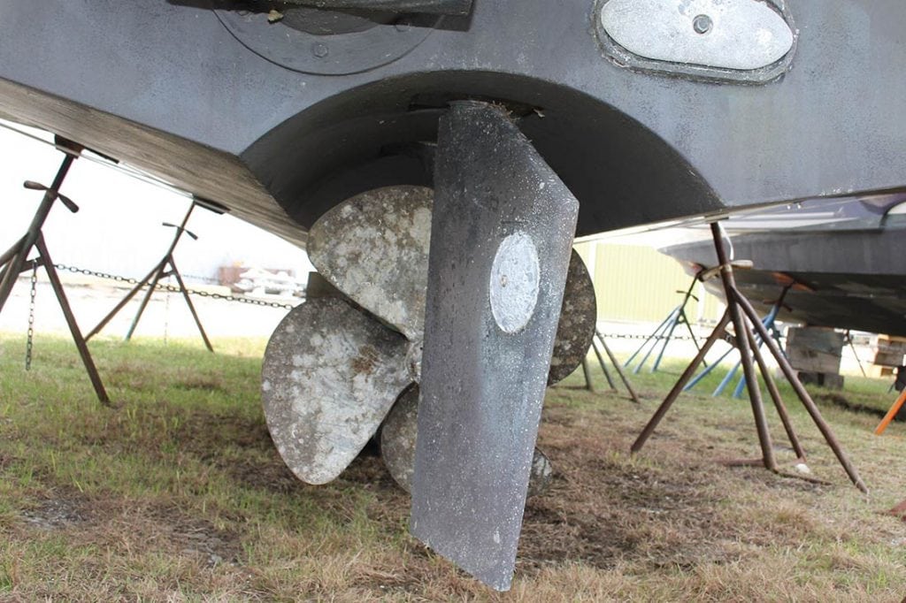
Figure 3 is an even better solution in that the skeg/keel is cut away in front of the propeller, allowing the water streamlines to flow more efficiently toward the prop. The rudder is taken up to the hull, and the skeg is deep enough that the propeller is protected. From a design standpoint, it would be smart to have a strut from the bottom of the keel to support and protect the bottom of the rudder, but you can’t have everything.
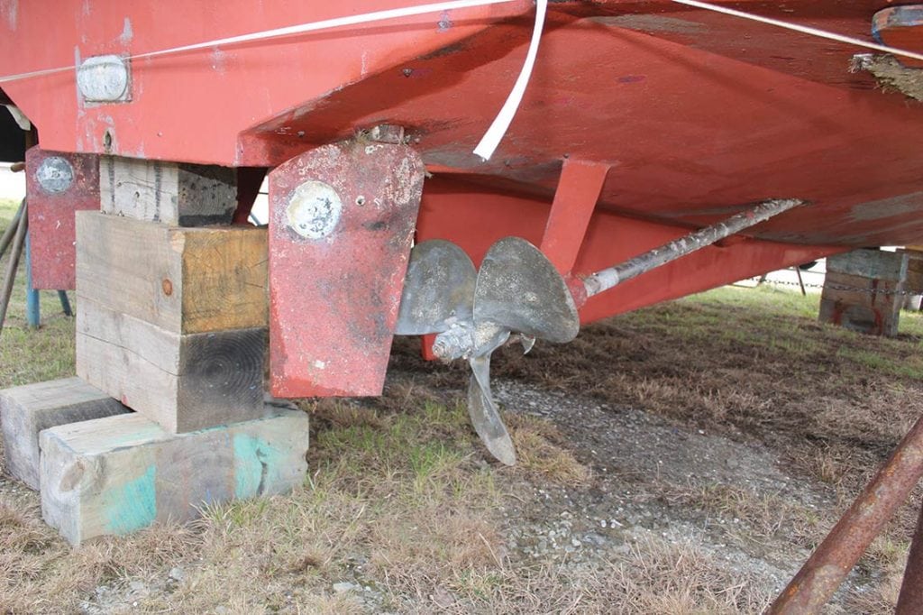
A far better solution—but one that uses more fuel—is the twin engine installation shown in Figure 4 (see opening header). Even though twin engines use more fuel, the efficiency of the exposed propellers is greater. Notice the keel is slightly deeper than the bottom of the propeller and only the prop shaft interrupts the flow of water to the propeller blades. The rudder is directly in the path of the propeller blade and operates at high efficiency.
All of these solutions, however, increase the boat’s draft. To reduce draft, many builders install a tunnel in the hull as shown in Figure 5. (Keep in mind that to reduce vibration and hull/propeller interaction, there should be at least 10 percent of the propeller diameter clearance between the hull and the blade tip.) By locating the prop in a tunnel, draft is reduced and some efficiency from the end plate effect of the hull is gained. However, Figure 6 shows how not to install a prop in a tunnel.
It would appear that the tunnel was built into the mold and either the designer did not take into account the width of the engine, or larger (and wider) engines were installed, pushing the shafts farther outboard. The propeller appears to be much smaller and farther away from the tunnel thus reducing its efficiency and increasing fuel consumption. The prop and rudder are both deeper than the hull and will be the first parts to hit should the boat go aground.
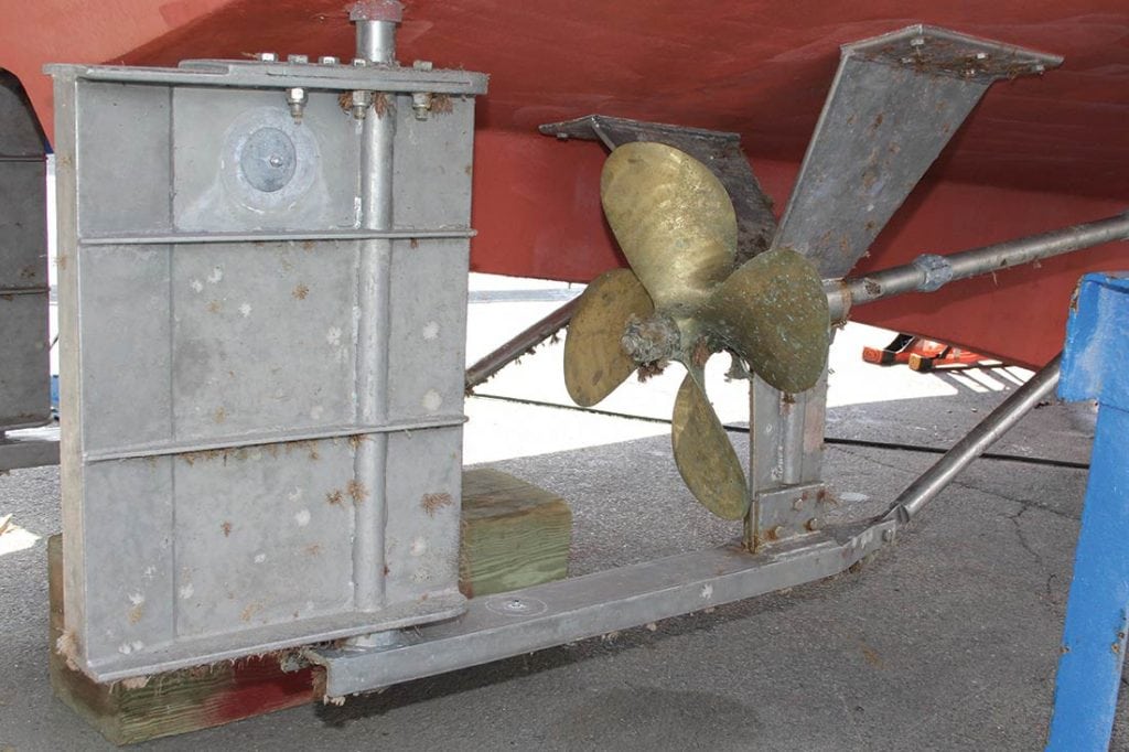
Finally, we come to Figure 7. The boat builder has taken great pains to ensure moderately clean water gets to the propeller but has then added an additional strut and inverted U-bar protection for the propeller and rudder. The rudder has several horizontal fins to either redirect water flow across the rudder or structurally strengthen the vertical portion of the rudder blade. All of these additional fins add resistance and increase fuel consumption.
Outboard Installations
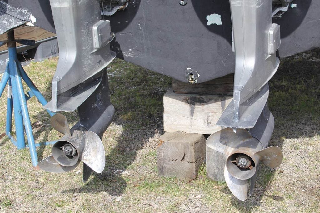
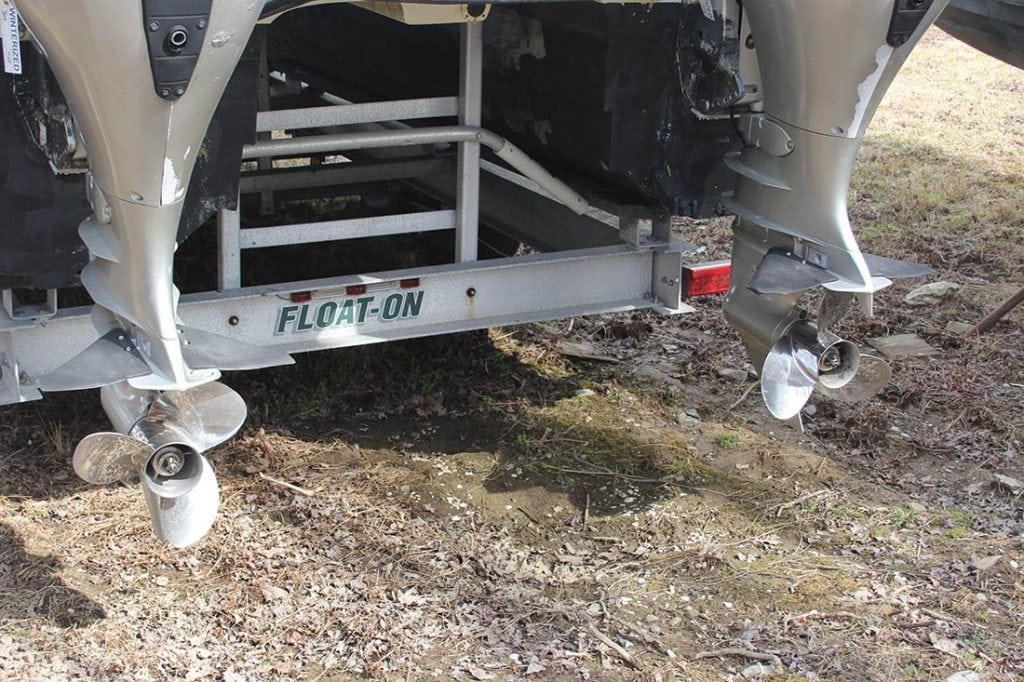
The beauty of an outboard installation is that the engine can be installed at any height to locate the prop below the hull. Figure 8 shows a pair of outboards installed with the anti-ventilation plate about level with the boat bottom. This puts the propellers in water flow that’s only obstructed by the lower gear case. The anti-ventilation plate is designed to prevent air from being sucked down the lower unit and into the propeller where it can cause loss of thrust. The outboard in Figure 8 is at exactly the right height for a moderate speed. Figure 9 shows a similar set up on a catamaran hull with the anti-ventilation plates right at the hull bottom.
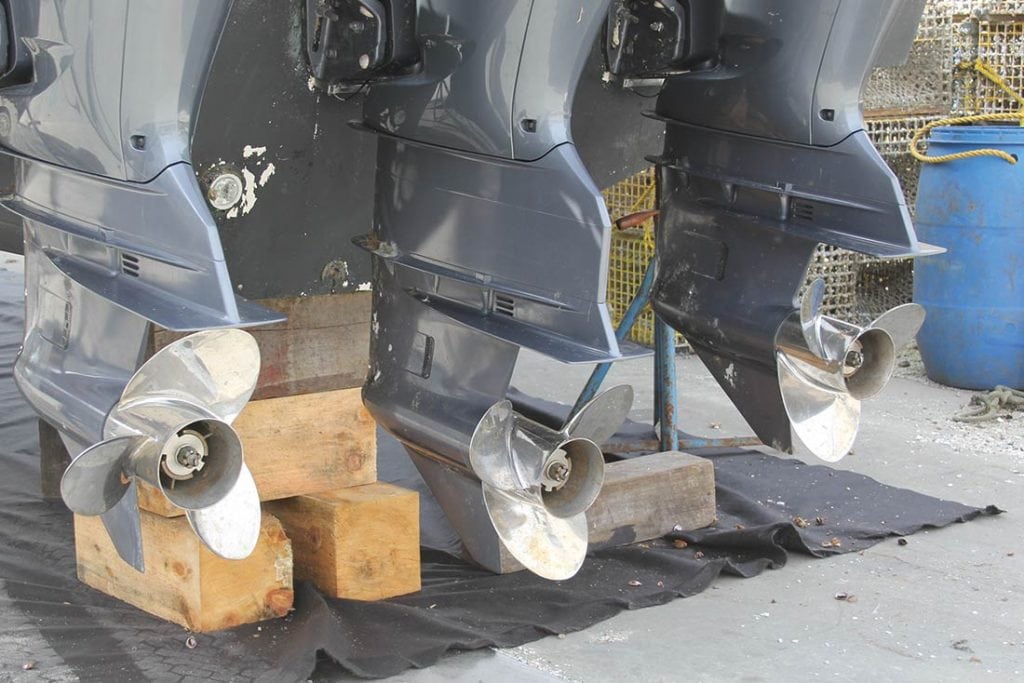
On faster vessels, the anti-ventilation plate is often located two to three inches above the boat bottom, but putting the engine higher may result in poor cooling water intake and an overheated engine, so care must be taken to locate the engine correctly. Figure 10 shows a faster speed hull with triple outboards. Notice how the anti-ventilation plates are about three inches higher than the hull bottom. On faster hulls, the strut/propeller/rudder drag (or resistance) is the largest single factor holding the boat back. For this reason, the shafts might pass through the transom to reduce drag, with the propellers some distance astern of the hull.
Another common case occurs when the propellers are supercavitating props with a straight trailing edge to reduce cavitation and loss of thrust. Arneson drives are typical of this drive train. To reduce drag on the fastest of hulls, only the lower half of the propeller is in the water. The shafts are then turned to steer the boat, eliminating rudder drag.
Roger Marshall, Southern Boating Magazine June 2016