Understanding Lightning Mitigation for Boats
Techniques to lessen the impact of a lightning strike
Having lived on the Chesapeake Bay for more than 20 years, 11 of them managing a boatyard that routinely repaired lightning-damaged vessels, I’ve learned a lot about lightning and its capricious nature as well as the damage this atmospheric phenomenon can produce, especially on boats without proper lightning protection.
When describing lightning, calling it unpredictable is an understatement. If anyone tells you they can predict what lightning will do, you should be suspicious. I’ve seen a monohull sailing vessel struck by lightning, causing the stainless steel VHF whip antenna to melt, dropping slag into the cockpit where it burned the dodger and gel coat. The VHF radio remained fully functional, and there was virtually no other damage save for a few burned-out light bulbs. This vessel was fully bonded (more on that shortly). I’ve also dealt with a catamaran that was struck. A plastic transducer was blown out of the hull, causing the vessel to flood and settle to the bottom at its dock, among other damage. It had no bonding system.
Adopting Standardized Lightning Protection for Boats
Fortunately for boat owners, builders, and yards, there is an objective third-party standard that is designed to help reduce, if not eliminate, injury and damage caused by lightning strikes, both direct hits and near misses. The American Boat and Yacht Council’s (ABYC) Standards, Chapter TE-4 “Lightning Protection” spells out guidelines that are primarily designed to keep those aboard safe from injury and fire caused by lightning strikes. To be clear, this system does not prevent lightning strikes (whether or not any system is capable of doing that is hotly debated); it is instead designed to safely channel them to the water on which the vessel floats. A variety of products have been, and continue to be, marketed that claim to prevent strikes.
Key Components of a Boat's Lightning Protection System: Wiring, Air, and Ground Terminals
Bonding systems are typically designed to prevent corrosion, however, when used in conjunction and compliant with a lightning protection system, they can improve safety and reduce damage. Bonding systems connect underwater metals, deck gear, spars, rigging, towers, tanks, and equipment enclosures, among other things.
One of the features of a lightning strike is the possibility of a side flash, essentially a lightning bolt that passes laterally within the vessel, potentially through a crew member or a combustible structure such as wood, fiberglass, or fabric. When using the proper gauge wire to connect underwater metals and the above-mentioned components as a part of a lightning protection system, the chance of a side flash can be significantly lowered.
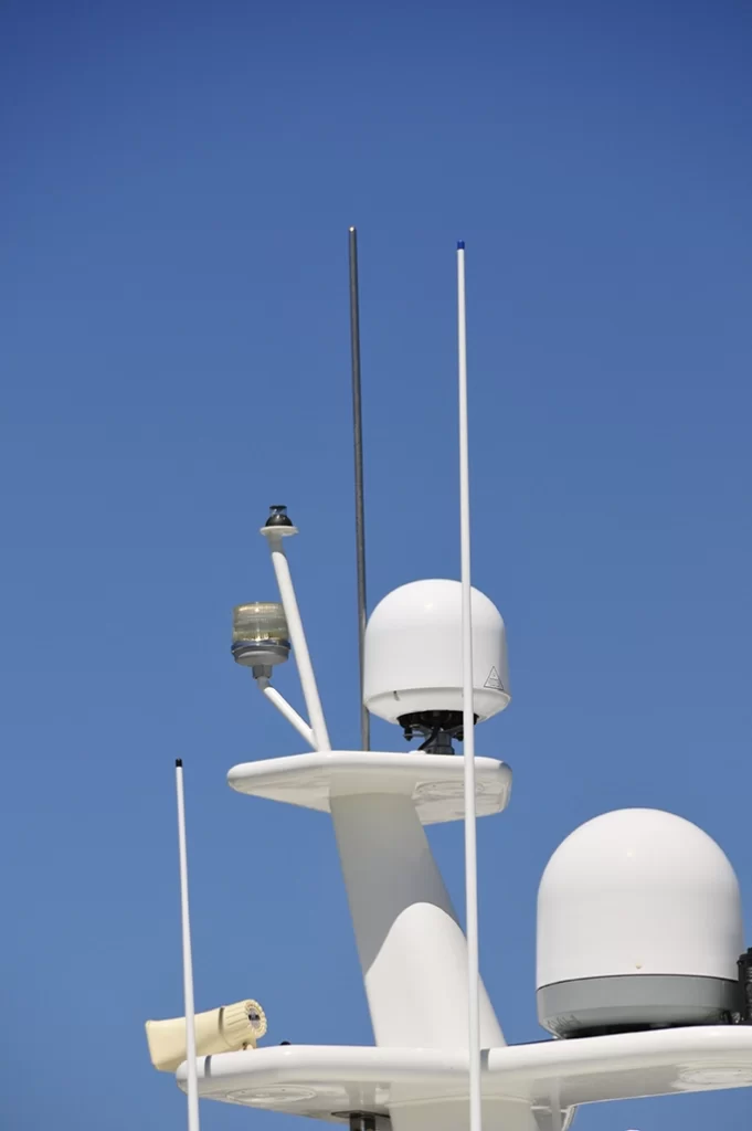
Much like a structure ashore, a vessel’s lightning system must possess two important elements, an air terminal and a ground terminal. The air terminal is “…a device at the uppermost point of the lightning protection system that attaches a lightning strike to the lightning ground system.” It is designed to bridge the gap between a lightning bolt and the vessel. Air terminals should be made from solid 3/8-inch copper or a ½-inch aluminum rod (the latter is better suited to aluminum spars), the top should be domed, and it should stand six feet above the masthead or other ungrounded or non-conductive structures (essentially everything).
The ground terminal, which represents the other end of the system, is the connection between the vessel’s lightning protection system and the sea. These must be metal and can be made from copper, copper alloy, aluminum, stainless steel, or lead, with a minimum thickness of 3/16 inches and 1 square foot of surface area.
Existing underwater appendages can fill this requirement, particularly an exposed ballast keel, struts, and rudders, provided they are nearly directly under the down conductor. In most cases, that excludes everything but a keel or a dedicated ground plate; however, these other submerged objects may be electrically tied to the ground terminal, augmenting its effectiveness.
For stand-alone, dedicated ground terminals, TE-4 calls for the edges to be square, or sharp, rather than radiused and not filleted with caulk or fairing (the leading edge can be rounded) for maximum dissipation effectiveness. Some studies indicate that the edge is what dissipates the strike, so the longer it is the better, making a rectangle more desirable than a square. My preference is for a solid ¼-inch-thick, 1- or 2-inch-wide copper strip—a band of sorts—that runs parallel with the vessel’s centerline, amidships, or beneath the mast or air terminal, that totals a minimum of 1 square foot of surface area. Thru-bolts connect this to the hull, with one serving as a connection point for the primary conductor from the air terminal, as well as for secondary conductors from other bonded gear and underwater metals.
Wiring that connects the air terminal to the ground terminal should be tinned, stranded copper and a minimum of #4 AWG (American Wire Gauge). It should be routed as straight and directly downward as vessel design permits. Under no circumstances should it make sharp bends—a sharp turn in this wire could lead to a side flash. If bends are necessary, they should never exceed 90 degrees with radii no less than eight inches. Additional wiring associated with the lightning system, from deck gear, stanchions, rails, etc., should utilize #6 AWG. Generally, at least where ABYC compliance is sought, all other bonding wires should be #8 AWG.
While it depends a great deal on the vessel’s design, with moderate investment, lightning “hardening” is possible, and it’s always easier to include it during the build rather than after-market.


